STM: more technical details
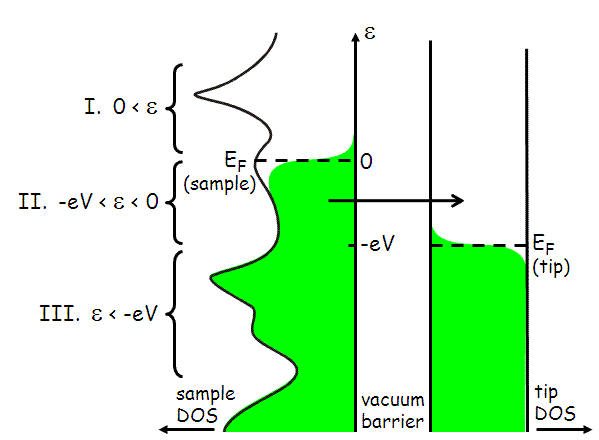
The tunneling current which flows between the tip and the sample depends on the voltage difference between the tip and sample. If the sample is biased by a negative voltage -V with respect to the tip, this effectively raises the Fermi level of the sample electrons with respect to the tip electrons. Electrons will tend to flow out of the filled states of the sample, into the empty states of the tip. This situation is illustrated below.

Fig 1: Schematic of tip-sample tunneling. Energy is along the vertical axis, and density of states of the sample and tip are shown along the horizontal axes. Filled states are shown in green. In this case, a negative bias voltage -V has been applied to the sample, which effectively raises its Fermi level by eV with respect to the Fermi level of the tip. This allows for filled states on the left (sample) to tunnel into empty states on the right (tip). The tunneling current is measured by an external circuit.
The elastic tunneling current from the sample to the tip for states of energy ε (with respect to the Fermi level of the sample) is:

where the factor of 2 out front is for spin, -e is the electron charge, 2ε/ℏ comes from time-dependent perturbation theory, |M|2 is the a matrix element, and f(ε) is the Fermi distribution:

Though the dominant tunneling current for negative sample voltage -V will be from sample to tip, there will also be a smaller tunneling current of electrons from tip to sample, which we can write in a similar fashion. When we sum these, and integrate over all energies ε, we arrive at the total tunneling current from sample to tip:

We can simplify this expression in several ways. First, if the measurements are made at low temperature, the Fermi function cuts off very sharply at the Fermi surface, with a cutoff width of kBT, which is only 0.36 meV for T = 4.2 K. In the approximation of a perfectly abrupt cutoff, the integral breaks into 3 parts, labeled I, II, and III in Fig. 1.
Therefore, the relevant range of e over which we must integrate to find the tunneling current is reduced to region II, where -eV < ε < 0. (Likewise, if we had applied a positive bias voltage V to the sample, our range of integration would be 0 < ε < eV.) So we are left with approximately:

Second, we pick a tip material which has a flat density of states within the energy range of the Fermi surface that we wish to study. For example, if we wish to study the sample density of states within 200 meV of the Fermi surface, then the measured tunneling current will be a convolution of the density of states of the tip and sample in this energy range. So we pick a tip material which has a flat density of states in this range, so that ρt(ε+eV) can be treated as a constant and taken outside the integral.

Bardeen first laid out a basic theory for vacuum tunneling in 1961. Perhaps most importantly, he showed that under the realistic assumptions that (1) the tip and the sample each have their own independent density of states, (2) each of their wavefunctions fall exponentially to zero in the tunneling barrier, and (3) the overlap is small enough (i.e. tip-sample separation is large enough) that each side is insignificantly influenced by the tail of the wavefunction from the other side, then the matrix element for tunneling will be virtually independent of the energy difference between the two sides of the barrier. In other words, to a reasonable approximation, we can take the matrix element outside the integral and treat it as a constant.

But what is |M|2? The matrix element comes from the assumption that both tip and sample wavefunctions fall off exponentially into the vacuum gap. Basically, we assume that the vacuum barrier is a square barrier, and we do a WKB approximation. In reality, there will be some tilt to the top of the barrier, but the tilt will be the applied voltage (on order 100 meV) while the height of the barrier will be on order the energy required to remove an electron from a metal, i.e. the work function, of several eV. Therefore, the tilt of the barrier will be much smaller than the height of the barrier, and can be ignored.
WKB says that the tunneling probability through a barrier will be |M|2 = e-2γ where:

where m is the mass of the electron, s is the width of the barrier (tip-sample separation), and φ is the height of the barrier, which is actually some mixture of the work functions of the tip and sample.
We can measure the work function by recording the tunneling current as a function of tip-sample separation.

Therefore, we can measure φ from the slope of lnI vs. s. Typically, we find φ is approximately 3-4 eV. The higher φ, the more the tunneling current will vary for a given change in s, therefore a higher φ gives a better resolution tip.
However, due to the exponential fall-off, we have no way of measuring the absolute value of s. This at times causes us much grief, because there is no way to know for sure if we are making measurements at a constant tip-sample separation. So if we see variation from one point on the sample surface to another, we can't be sure whether the variation is due to intrinsic inhomogeneities in the sample at the specific energy of measurement, or due to a varying tip-sample separation.
In summary, the tunneling current is fairly well approximated by:

[Measurements that can be made with an STM]