Spin-Polarized
Scanning Tunneling Microscopy
A spin-polarized scanning tunneling microscopy (SP-STM) is an STM that is sensitive to the spin orientation of tunneling electrons. This allows us to make atomically resolved images of the magnetic order in a material.
Recall that an STM measures the local density of electronic states in a sample by tunneling through an atomically sharp tip positioned a few Ångstroms above the sample surface. The total tunneling current is proportional to the integrated density of states between the Fermi level and the relative tip-sample voltage.
A spin-polarized scanning tunneling microscope (SP-STM) employs much the same technique, but makes use of a magnetic tip to provide a source or sink of spin-polarized electrons for tunneling.
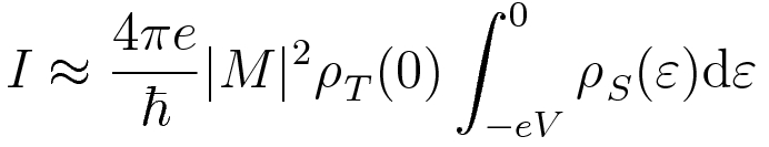
We can think of the current as the sum of two separate spin channels, illustrated in Figure 1. To a good approximation, we assume that no electrons flip their spins while tunneling.

As in a traditional STM, |M|2 is the tunneling matrix element, and falls off exponentially with tip-sample distance. The spin-up density of states ρ↑T(ε) refers to the number of spin-up states per unit energy and volume in the tip. If the tip DOS is approximately constant in the energy range of interest around the Fermi level, the SP-STM probes the local spin-polarized density of states in the sample.
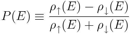
We can define a quantity known as the spin-polarization of the tip or sample:
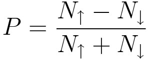
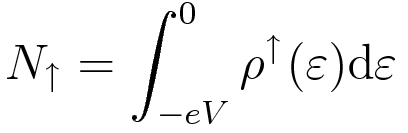
P can range from 0 to 1. In Figure 1, for instance, PT≈20% and PS≈90%. With this definition, the tunneling current can be expressed as
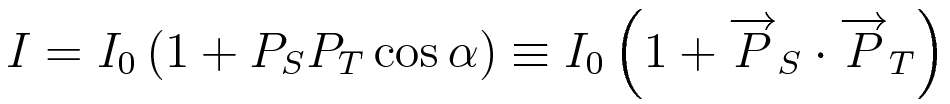
where I0 is the spin-averaged current and α is the angle between the tip and sample magnetization, as shown in Figure 2. To get the best magnetic resolution, we want the tip and sample to be magnetized along the same axis.
Fig. 2 When magnetization axes of tip and sample are misaligned by an angle α, the tunneling current is proportional to (1+PSPTcosα).
As with the density of states, spin polarization is a local quantity that may vary with position. If our sample is an antiferromagnet, PS will change direction with each unit cell. Imaging in constant current mode ("topographic" mode), this magnetic order causes an apparent difference in height, where "tall" atoms alternate with "short" ones. We can verify that the apparent modulation in height is due to magnetic order (and not some other effect) by changing the direction of the tip polarization.
If we instead image the differential conductance (dI/dV), the measured quantity is the energy-resolved spin polarization:
For some materials a dI/dV map provides a stronger magnetic signal than topographic image.
To obtain spin-resolved images, we need a source of spin-polarized electrons. Specifically, we need the tip atom that is closest to the sample to have a well defined spin-polarization. Since exchange splitting causes spin-polarization in magnetic metals, the Hoffman lab will explore several options:
- Ferromagnetic materials, such as Nickel and Iron
- Antiferromagnets, such as Chromium and Manganese.
- A thin film of either a ferromagnet or antiferromagnet. Other labs have found that the preferred magnetization axis can depend on thickness of the film (see Wiesendanger, Rev Mod Phys 2009).
- "Dunking" a nonmagnetic tip into a magnetic sample, to pick up a few spin-polarized atoms on the tip.
There are several trade-offs among these tip designs: ease of producing the tip, ability to stabilize, reproduce, and quantify the magnetization, ability to flip the magnetization with an applied field, and presence or absence of stray fields from the tip.