Properties of
Bechgaard Salts
Crystal Structure
Molecular conductors are formed from building blocks of carbon bonded to oxygen, selenium and/or sulfur. Unlike a conventional metal, the molecular compounds are retained crystal structure and thus it is relevant to study these subunits of the overall structure. Moreover, we can learn a great deal about the overall conductivity and electronic properties by evaluating the geometric properties of the individual molecules and the stacking to form the three-dimensional crystal lattice. The "TMTSF" or tetrametyltetraseleniafulvalene molecule, the building block of the Bechgaard salts, is shown in Figure 1. (Carbon is black, selenium orange and hydrogen white).
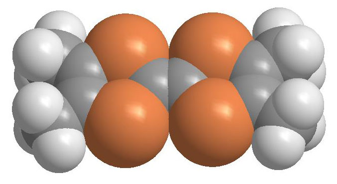
Fig. 1 This shows the structure of the TMTSF molecule. Put your mouse over the image for the view from a different angle.
The Bechgaard salts are a class of charge transfer compounds in which one electron from a pair of TMTSF molecules is transferred to the anion--the resultant positive charge on the TMTSF molecules is shared throughout the structure due to the dense packing of these flat donor molecules. The negative charges are shared on the channels of anions separated from the TMTSF molecules. In addition, the size of the anion molecule chosen dictates the spacing of the TMTSF columns and thus has an effect similar to that of an applied pressure as seen on the phase diagram. In short, both the crystal structure and the geometry of the individual TMTSF molecule are critical in ensuring the charge transfer throughout the bulk sample.
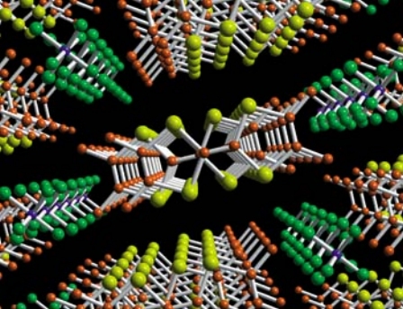
Fig 2 Carbon shown in orange, selenium in yellow, potassium in blue, and fluorine in green. Figure taken from Claude, Jerome, Physics World (1998).
The crystal structure of (TMTSF)2PF6 is shown at left with the a-axis (the stacking axis with the highest conductivity) perpendicular to the plane of the image. The TMTSF and TMTTF families both exhibit this crystal structure with stacks of organic molecules separated by the columns of negatively charged anions. The organic molecules are nearly flat and aligned in a zigzag pattern down the a-axis with a slight dimerization (the molecular orbital picture described below highlights the overlap with this alternations). The small distance between one stack and the other in the b direction leads to a slight overlap in this direction and a weak 2-D character as pressure increases.
In addition, the orientation and symmetry of the anion can have a large impact on the overall properties. For the non-centrosymetric anions, those without an inversion center, such as ClO4 and FeO4, there are two relative orientations of the anions with respect to the surrounding molecules with equivalent energies. At high temperatures, we see a thermal mixture of both forms. However, at lower temperatures the structure can undergo a disorder → order transition if cooled sufficiently slowly such that all the anions are ordered in the same fashion.
Electronic Structure
Electrical Conductivity: Molecular Orbital Picture
Electrical conductivity in the Bechgaard salts arises under normal conditions because each pair of TMTSF or TMTTF molecules donates an electron to the anion acceptor. In most cases the negatively charged anion forms a closed shell and does not contribute to the overall conductivity, so current is carried by the holes created on the TMTSF or TMTTF chains, and the conductivity depends on the hole density and the complementary mobility.
Fig. 3 This figure shows the orbital shapes for one TMTSF molecule. Put your mouse over the figure for a different view.
The mobility of the holes depends on the overlap of the bonding orbitals of the TMTSF or TMTTF molecules and thus their ability to delocalize the hole throughout the structure. In addition to the underlying framework of single bonds lying in the plane of the molecule, each of the carbon and selenium atoms has a perpendicular p orbital. These orbitals overlap to form the molecular π structure perpendicular to the plane in which all the p-electrons of the molecule are delocalized. Moreover, by adding these p-orbitals in different phase combinatoins, we can build up a set of molecular orbital energy levels. The figure on the left shows the partially occupied orbital (after the loss of an electron to the anion).
Fig. 4 This shows the molecular orbital shapes along a stack of TMTSF molecules.
In addition to being delocalized throughout the individual molecule, this π electron can also be shared between many molecules in the chain along the a-direction. Although technically the orbitals should be constructed for the entire molecule, the intramolecular bonding is still much stronger than the intermolecular effects and thus the individual molecule approximation effectively produces the character of the bonding. From the figure on the right, we can see that the molecular orbitals from adjacent molecules in the chain overlap constructively to form an electronic band. This strong overlap leads to a large bandwidth and therefore conductivity throughout the structure.
In addition, this picture explains why the conductivity in the a-direction is 10 and 100 times stronger than in the b and c directions, respectively. However, the addition of pressure, either chemical or mechanical, pushes the molecules closer together and increases the orbital overlap. Thus we see the emergence of quasi-2D and 3D behavior at high pressures on the phase diagram. In addition, the selenium atom has a larger p-orbital than the sulfur atom and therefore charge is more readily transferred in the TMTSF structures than in the TMTTF based ones.
Electrical Motion: Quasi-1D structures
We can also look at the electronic motion from the perspective of a 1D material in the tight binding approximation rather than building up from the individual molecular compounds . A perfectly 1-dimensional structure would have a flat Fermi surface, a projection of which is shown on the left in Figure 5. However, there is a non-negligible interstack transfer (i.e. interactions in the b-direction) which cause the Fermi surface to warp, an exaggeration of which is shown on the right in Figure 5.
Accessible Phases
As a function of temperature, pressure, and magnetic field the Bechgaard salts can access almost every phase known to condensed matter physicists. In addition, this group of materials shows remarkable interplay between chemical substitutions applied pressure. Namely, we see the different compounds in the class stretching across the top access of the phase diagram from the thiol (sulfur) based compounds on the left to the selenium based compounds on the right with differing anions. The positions of the arrows represent the ground state of each compound with no applied pressure. For example, the ground state of (TMTSF)2ClO4 is nearly the same as (TMTSF)2PF6 under about 10 kbars of pressure. This intermingling between the effects of pressure and chemical substitutions helps us both further experimenally access and understand the properties of the multitude of states and the physical effects of chemical substitutions.
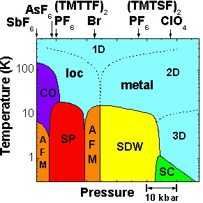
Guide to the states listed in the above diagram
Fig. 7 Cartoon showing the spatial organization of magnetic moments in the AFM phase.
AFM: The anti-ferromagnetic phase. The electrons have magnetic moments arranged in an alternating pattern, so that the magnetic moments are ordered but the combined magnetic moment is zero. See the diagram at the right.
CO: The charge-ordered phase.
loc: Here, the electrons are localized in the crystal, so it acts as an insulator.
metal: In this state the material acts as a metal. A large number of electrons are de-localized and can carry charge easily. The dimension (1D, 2D, 3D) indicates the number of dimensions along which current can easily flow.
SC: The superconducting state. Current flows along one or more axes with zero resistance in this state, which is described in detail in the background section.
SDW: The spin-density wave state. In this state, the electronic spin density forms a static wave, alternating over regions containing large numbers of electrons. Although local areas have parallel spins, there is no net magnetization on the crystal.
SP: The spin-peierls state. The spin-Peierls state is an antiferromagnetic state in which the spin moments magnetoelastically couple to the lattice vibrations. The lattice dimerization causes an energy gap in the magnetic excitations.

Funding for organic superconductor research in the Hoffman lab was provided by the National Science Foundation under grant number DMR-0508812.
This organic superconductor website was written by former undergraduates Julia Mundy and Sam Cross.